The Name And Function Of Each Part Of The Placement Machine
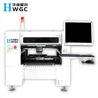
1. Host
1.1 Main Power Switch: Turn on or off the host power
1.2 Vision Monitor: Displays the recognition of images or components and marks obtained by moving the lens.
1.3 Operation Monitor: Display the VIOS software screen of the machine operation. If there is an error or problem during the operation, the correction information will also be displayed on this screen.
1.4 Warning Lamp: Indicates the operating conditions of the placement machine in green, yellow and red.
Green: The machine is in automatic operation
Yellow: Error (return-to-origin cannot be performed, pick-up error, recognition failure, etc.) or an interlock occurs.
Red: The machine is in emergency stop state (the machine or YPU stop button is pressed).
1.5 Emergency Stop Button: Press this button to immediately trigger an emergency stop.
2. Head Assembly
Work Head Assembly: Move in XY direction (or X direction), pick parts from feeder and place on PCB.
Head Assembly Movement Handle: When the servo control is released, you can move in every direction with your hands. This handle is usually used when moving the head assembly by hand.
3. Vision System
Moving Camera: Used to identify marks on the PCB or to track positions or coordinates.
Single-Vision Camera: Used to identify components, mainly those QPFs with pins.
Backlight Unit: Illuminates the element from the back when identified with a separate vision lens.
Laser Unit: The laser beam can be used to identify parts, mainly sheet parts.
Multi-Vision Camera: It can identify multiple parts at one time, speeding up the identification speed.
4. FeederPlate:
Tape feeders, bulk feeders, and tube feeders (multi-tube feeders) can be installed on the front or rear feeding platform of the placement machine.
5. Axis Configuration
X-axis: The moving head assembly is parallel to the PCB transfer direction.
Y axis: The moving head assembly is perpendicular to the PCB transfer direction.
Z-axis: Controls the height of the head assembly.
R axis: Control the rotation of the nozzle axis of the work head assembly.
W axis: Adjust the width of the transport rail.
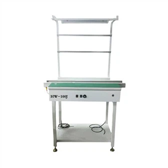
6. Conveyor Unit
1. Main Stopper
2. Locate Pins
3. Push-in Unit
4. Edge Clamp
5. Push-up Plate
6. Push-up Pins
7. Entrance Stopper
7. Nozzle Station: Allows automatic exchange of nozzles, can load a total of 16 nozzles, 7 standard and 9 optional nozzles.
8. Air Supply Unit
Including air filter, air pressure adjustment button, air pressure gauge.
9. Data Input and Operation Devices
1. YPU (Programming Unit) programming unit
Ready button: Cancel the abnormal stop and activate the servo system.
2. The function of each key of the keyboard (Keyboard)
F1: Help for real-time options
F2: Used in the transition of PCB production
F3: Convert the programming target (component information, placement information, etc.)
F4: Convert the sub-window (shape, recognition, etc.)
F5: used to jump to the data address
F6: used for auxiliary adjustment
F7: set database
F8: Visually display the physical outline
F9: photo location
F10: Coordinate tracking
Tab: switch between windows
Insert, Delete: Change the parameters of the sub-window
↑↓→←: cursor movement and text page UP/Down movement
Space Bar: Pause the machine during operation (press again to unpause)
Notice:
1) Master the name of each part, compare it with the actual machine, and point out the name and basic function of which part.
2) When an emergency occurs, which button should be pressed, the status of the warning light and the display of the operation display?